Introduction
In a Cisco SD-WAN fabric, transport resiliency and efficient use of transports are critical for delivering reliable connectivity. Each WAN Edge in the fabric typically connects to one transport network, like MPLS, Internet, 4G/5G, etc. The unique logical combination of System-ip + Color + Encapsulation result in what are known as Transport Locators (TLOCs).
However, on dual router scenarios, not every branch site has the luxury of multiple WAN circuits connected to a single router. In some cases, one WAN circuit may be terminated on one router, while another circuit is only available on a second router. This is where TLOC Extension comes in, allowing one router to leverage the transport connection of another router in the same site, increasing tunnel redundancy and flexibility.
Let’s explore it in more detail.
What is TLOC Extension?
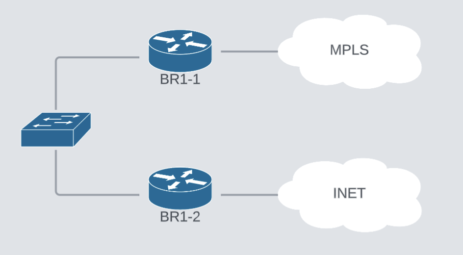
TLOC Extension in Cisco SD-WAN enables a router to use the transport interface of another router as if it were its own. This is done by extending the TLOC (Transport Locator) from one router to another through a Layer 2 or Layer 3 connection. The physical representation looks like this:
In practice, this means Router A can leverage Router B’s transport circuits (for example, MPLS or Internet) without being directly connected to them, and vice versa. This mechanism ensures that all routers at the site can fully use all the available transports in the SD-WAN fabric, even if they don’t have their own dedicated transport connections. The logical picture is something like this:
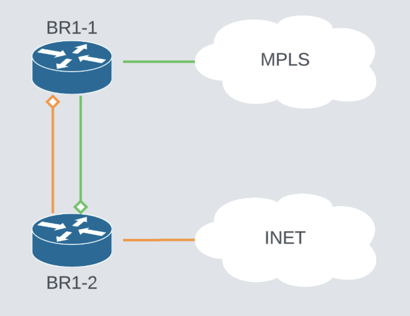
BR1-1 can now use INET as transport and BR1-2 can use MPLS as an available transport as well.
Some of the advantages of using TLOC extension:
- It reduces the direct number of circuits you need per router.
- It provides resiliency at the site level.
- It simplifies deployments in branch offices where only one transport circuit is physically available.
Use Cases
TLOC Extension addresses real-world challenges in SD-WAN deployments. Some common use cases include:
Small Branch Sites with Limited Connectivity
A branch may only have a single Internet or MPLS link. With TLOC Extension, two routers can still operate with redundancy by sharing that single transport.
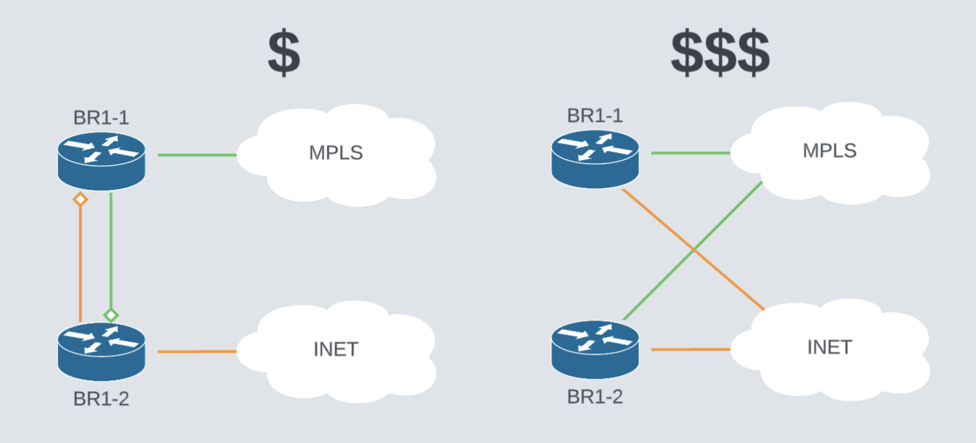
Cost Optimization
Instead of purchasing multiple circuits for each router, costs can be reduced by having one circuit per transport type and sharing it across routers.
Transport Redundancy
When a site has different transport types split across different routers (Example: Internet on Router A, MPLS on Router B), TLOC Extension ensures both routers can access both transport types.
Architecture and How it Works
A TLOC is defined by three elements:
- System IP of the router
- Color (which transport type the link belongs to, e.g., public-internet, mpls, lte)
- Encapsulation (IPsec/GRE)
With TLOC Extension, one router establishes an internal tunnel across the LAN to another router, allowing it to advertise and use that TLOC.
Key points about the architecture:
- A TLOC extension is built over a physical LAN interface between the two routers, sub-interfaces and dot1Q encapsulations are commonly used.
- The “donor” router provides access to its transport interface.
- The “receiver” router can then form control and data plane connections using that transport.
From a fabric perspective, both routers appear as if they were independently connected to the transport cloud.
Configuring TLOC Extension
I will take advantage of the UX 2.0 guided workflows to quickly generate a configuration for a dual-router site with TLOC extension and we’ll examine it.
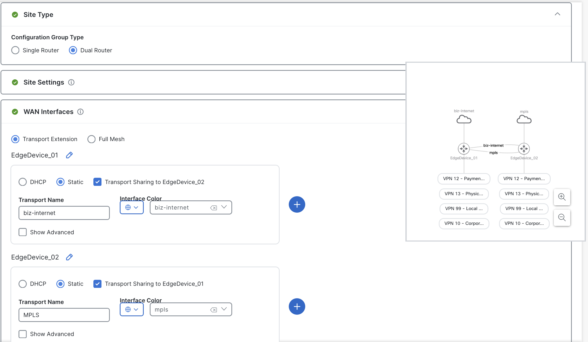
The resulting configuration has the following interfaces on the Transport Feature Profile.
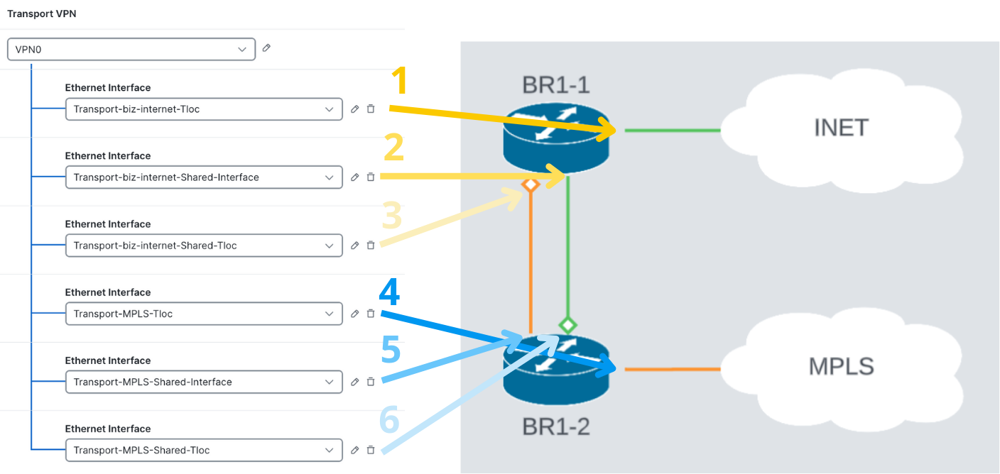
Six different interfaces were created, let’s examine three of them to understand how TLOC extension is configured.
Note I needed to remove some unneeded NAT on some of those interfaces, aside from this, configuration was ready.
Interface #1 - Internet TLOC on BR1-1
The first interface connect directly to the Internet Transport, standard interface and TLOC configuration.
interface GigabitEthernet1
 description WAN Interface - biz-internet
 ip address 31.11.0.2 255.255.255.252
 ip nat outside

sdwan
 interface GigabitEthernet1
  tunnel-interface
   encapsulation ipsec weight 1
   color biz-internet
Interface #2 - BR1-1´s “Donated” interface to BR1-2
The second interface is needed to extend Internet TLOC to BR1-2, it needs an ip address and BR1-2 will use it as a default gateway.
interface GigabitEthernet4
 description WAN Interface - biz-internet
 ip address 172.17.1.6 255.255.255.252

sdwan
interface GigabitEthernet4
  tloc-extension GigabitEthernet1
 exit
Interface #6 - Extended Internet TLOC on BR1-2
This is a normal TLOC configuration that will use BR1-1’s IP address as default gateway for the biz-internet transport.
interface GigabitEthernet5
 description WAN VPN 0 Interface - biz-internet
 ip address 172.17.1.5 255.255.255.252
!
ip route 0.0.0.0 0.0.0.0 172.17.1.6

sdwan
interface GigabitEthernet5
  tunnel-interface
   encapsulation ipsec weight 1
   color biz-internet
The subnet 172.17.4.0/30 needs to be advertised on the MPLS underlay. Typically, BGP is used to do this advertisement.
The configuration of interfaces 3,4 and 5 are a mirror of what we just saw.
Validation
Once this configuration is in place, we can validate our control and data plane:
On BR1-1, notice that I have two different SD-WAN interfaces, Gig1 and Gig5
Lisbon_10-1#show sdwan control local-properties
personality                       vedge
sp-organization-name              MYSDWAN-LAB123
organization-name                 MYSDWAN-LAB123
root-ca-chain-status              Installed
root-ca-crl-status                Not-Installed
...
                         PUBLIC          PUBLIC PRIVATE         PRIVATE         PRIVATE                         MAX   RESTRICT/           LAST         SPI TIME    NAT  VM          BIND
INTERFACE                IPv4            PORT   IPv4            IPv6            PORT    VS/VM COLOR       STATE CNTRL CONTROL/     LR/LB  CONNECTION   REMAINING   TYPE CON REG     INTERFACE
                                                                                                                      STUN                                              PRF IDs
-----------------------------------------------------------------------------------------------------------------------------------------------------------------------------------------------------------------------------------------
GigabitEthernet1       31.11.0.2       12386  31.11.0.2       ::                12386    1/1  biz-internet     up     2      no/yes/no   No/No  0:00:00:10   0:03:06:00  N    5  Default N/A
GigabitEthernet5       172.17.1.5      12426  172.17.1.5      ::                12426    1/0  mpls             up     2      no/yes/no   No/No  0:00:00:15   0:04:19:53  N    5  Default N/A
Control connections work on both transports as expected
Lisbon_10-1#show sdwan control connections
                                                                                       PEER                                          PEER                                          CONTROLLER
PEER    PEER PEER            SITE       DOMAIN PEER                                    PRIV  PEER                                    PUB                                           GROUP
TYPE    PROT SYSTEM IP       ID         ID     PRIVATE IP                              PORT  PUBLIC IP                               PORT  ORGANIZATION            LOCAL COLOR     PROXY STATE UPTIME      ID
----------------------------------------------------------------------------------------------------------------------------------------------------------------------------------------
vsmart  dtls 1.0.0.3         999        1      10.1.0.4                                12446 10.1.0.4                                12446 MYSDWAN-LAB123          biz-internet    No    up     0:20:59:37 0
vsmart  dtls 1.0.0.3         999        1      10.1.0.4                                12446 10.1.0.4                                12446 MYSDWAN-LAB123          mpls            No    up     0:07:45:45 0
vbond   dtls 0.0.0.0         0          0      10.1.0.3                                12346 10.1.0.3                                12346 MYSDWAN-LAB123          biz-internet    -     up     0:20:59:38 0
vbond   dtls 0.0.0.0         0          0      10.1.0.3                                12346 10.1.0.3                                12346 MYSDWAN-LAB123          mpls            -     up     0:07:48:46 0
vmanage dtls 1.0.0.1         999        0      10.1.0.1                                12646 10.1.0.1                                12646 MYSDWAN-LAB123          biz-internet    No    up     0:20:59:38 0
My data plane also established using MPLS and Biz-internet
Lisbon_10-1#sh sdwan bfd sessions
                                      SOURCE TLOC      REMOTE TLOC                                      DST PUBLIC                      DST PUBLIC         DETECT      TX
SYSTEM IP        SITE ID     STATE       COLOR            COLOR            SOURCE IP                                       IP                                              PORT        ENCAP  MULTIPLIER  INTERVAL(msec  UPTIME          TRANSITIONS
-----------------------------------------------------------------------------------------------------------------------------------------------------------------------------------------------------------------------------------------------------
1.1.20.1         20          up          biz-internet     mpls             31.11.0.2                                       21.21.0.2                                       12346       ipsec  7           1000           0:07:48:41      0
1.1.20.2         20          up          biz-internet     mpls             31.11.0.2                                       21.22.0.2                                       12346       ipsec  7           1000           0:07:48:41      0
1.1.200.1        200         up          biz-internet     mpls             31.11.0.2                                       21.201.0.2                                      12346       ipsec  7           1000           0:21:01:36      1
1.1.200.2        200         up          biz-internet     mpls             31.11.0.2                                       21.202.0.2                                      12346       ipsec  7           1000           0:21:01:36      1
...
1.1.20.1         20          up          mpls             mpls             172.17.1.5                                      21.21.0.2                                       12346       ipsec  7           1000           0:07:47:43      0
1.1.20.2         20          up          mpls             mpls             172.17.1.5                                      21.22.0.2                                       12346       ipsec  7           1000           0:07:47:43      0
1.1.200.1        200         up          mpls             mpls             172.17.1.5                                      21.201.0.2                                      12346       ipsec  7           1000           0:07:47:43      0
1.1.200.2        200         up          mpls             mpls             172.17.1.5                                      21.202.0.2                                      12346       ipsec  7           1000           0:07:47:43      0
Considerations
When deploying TLOC Extension, consider the following:
Use Direct Connections Where Possible
A direct cable between routers is preferred over a shared switch to minimize failure points.
Use sub-interfaces if there aren’t enough interfaces
In situations where devices don’t have available ports, you can always do layer 2 TLOCs using sub-interfaces, just be mindful of the available bandwidth as the throughput will be shared.
Plan for Redundancy
Critical sites are better off with direct connections to available transports. TLOC extensions will help extend transports, but will not protect in case of device failures.
Advertise TLOC extension subnets
To provide your private tloc extensions with connectivity, the local subnet must be reachable on the private transport. You can use BGP, static or any other routing means to achieve it.
Avoid Overloading the LAN Link
The link between routers should be sized appropriately, as all extended traffic will traverse it.
Layer 3 TLOC Extension
Tlox Extension can be configured as layer 3 and GRE encapsulation. This is especially useful when two devices don’t have a direct layer 2 adjacency.
Conclusion
TLOC Extension is a powerful feature in Cisco SD-WAN that enhances flexibility and resiliency at branch sites. By allowing routers to share transport connections, it optimizes resource usage, lowers costs, and ensures that all routers can fully participate in the SD-WAN fabric, even when dedicated WAN links are limited.
Proper planning, redundancy, and monitoring are essential to get the most value out of this feature. When implemented correctly, TLOC Extension can significantly improve the robustness and cost-effectiveness of an SD-WAN deployment.
👉 Stay tuned for the next blog, where we’ll continue exploring practical ways to strengthen and optimize your Cisco SD-WAN design