Introduction
Have you ever used a business app that feels painfully slow. Maybe video calls freeze, or a web dashboard takes forever to load. These (and others) are signs that your WAN might be struggling under the hood.
The good news? Cisco SD-WAN includes a suite of powerful technologies designed to boost performance over unreliable or high-latency links. In this series, we’ll break down three key features that can significantly improve application experience across your network: TCP Optimization, Forward Error Correction (FEC), and Packet Duplication.
In this first post, we’ll explore TCP Optimization - how it works, when to use it, and why it can be a game-changer for your users, especially over high-delay connections.
What is TCP Optimization?
The goal of TCP Optimization is to fine tune TCP connections to improve the performance. This is especially useful when there are long-latency links involved.
The SD-WAN routers will act as proxies, meaning that they will intercept the TCP connections and tune them to get better performance. Let´s see a visual.
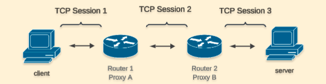
Without TCP optimization, the client and server will establish a TCP session directly between them.
When TCP Optimization is used, Router 1 will intercept and terminate the TCP connection from the client and establish a TCP session with Router 2 that will be optimized. Likewise Router 2 will create a TCP session with Server.
Note All this process is transparent to the client/server and data is going to be cached on the routers to keep the sessions alive.
The IOS-XE SD-WAN devices use BBR algorithm which uses information about RTT and available bandwidth to optimize the connection. If you’d like to learn more I would recommend checking this video from Neal Cardwell.
The current TCP Optimization implementation defines different device roles:
- Controller Node: Device that intercepts and distributes traffic to Service Nodes.
- Service Node: Optimization engines for traffic acceleration.
In a real world scenario the recommendation is to have optimization services on Branches and Data Centers. There are different requirements based on the volume of traffic those devices will handle. I suggest reading Cisco’s Documentation to understand platform requirements and more.
On the branches, it is common to use an Integrated Service Node meaning that a single device can intercept, distribute and optimize traffic. On the other hand, on the Data Center, a cluster of External Service Nodes is required to achieve higher throughput and distribute higher volumes of traffic amongst cluster members.
Overall TCP Optimization is an intensive process for the devices and it’s crucial to confirm platform requirements. For instance, my demo environment has two Catalyst 8000V with 8 CPUs and 16 GB of RAM, requirements for a small deployment.
Let’s see in practice what effect Optimization has on the traffic. To demonstrate it, I will take a packet capture on the WAN side with and without optimization:
Window Scaling Without Optimization
Let’s see how the window scaling behaves without optimization
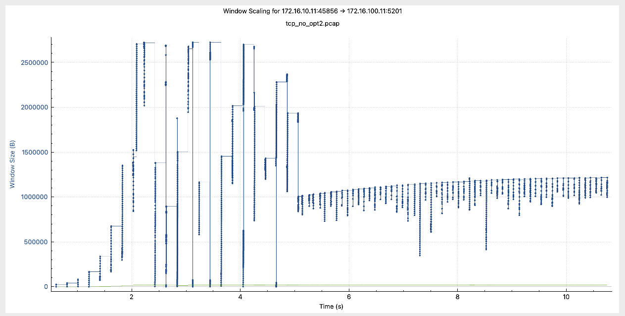
Notice that the window size remained mostly stable at around 1,000,000 Bytes after around 5 seconds
Window Scaling With Optimization
Let’s look at the same information with optimization enabled.
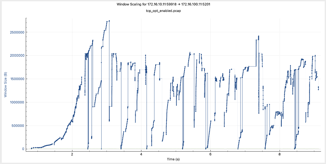
Notice how the window size remained changing throughout the session, quickly and aggressively recovering after going down.
Why is the window scaling so important? I asked ChatGPT to explain it simply and concisely:
Window scaling is crucial in high-latency or high-bandwidth networks because it allows TCP to use a larger receive window, which directly impacts how many bytes in flight (i.e., unacknowledged data) a sender can have. Without window scaling, the max window size is 65,535 bytes — too small for high-speed links, leading to underutilization. With window scaling, the window can grow to gigabytes, enabling the sender to keep more data “in flight” and maintain high throughput despite delays.
In summary, the TCP session is split into three segments, with the optimizing routers advertising higher window scaling and managing connections with the client and server. Traffic is now governed by the BBR algorithm to maximize throughput.
Configuration
To configure this feature, you can use either Feature Templates and Configuration Groups (with version 20.15 or above). In my case, I will use Configuration Groups and will make use only of Internal Service Nodes on both sides.
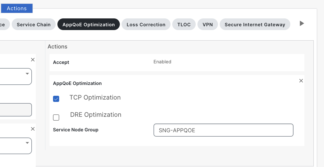
To start, I add the feature “App QoE” on the Service Profile with the following configuration:
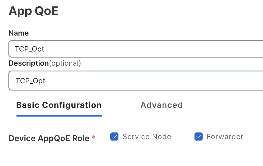
- Service Node to perform acceleration
- Forwarder to also act as a Controller Node
This creates the service node configuration
interface VirtualPortGroup2
  no shutdown
  ip address 192.168.2.1 255.255.255.0
  service-insertion appqoe
!
service-insertion appnav-controller-group appqoe ACG-APPQOE
  appnav-controller 192.168.2.1
!
service-insertion service-node-group appqoe SNG-APPQOE
  service-node 192.168.2.2
!
service-insertion service-context appqoe/1
  appnav-controller-group ACG-APPQOE
  service-node-group      SNG-APPQOE
  cluster-type            integrated-service-node
  enable
  vrf global
!
Status should be “Running”
Lisbon_10-1#show sdwan appqoe tcpopt status
==========================================================
                  TCP-OPT Status
==========================================================

Status
------
TCP OPT Operational State      : RUNNING
TCP Proxy Operational State    : RUNNING
Next, I create a simple data policy matching traffic between client and server and select the action to be AppQoE Optimization and check the box of TCP Optimization.
vsmart_1# show running-config policy
policy
 data-policy _VPN_10_AppQoE
  vpn-list VPN_10
   sequence 1
    match
     source-data-prefix-list      BR10_172_16_10_0
     destination-data-prefix-list DC_100_172_16_100_0
    !
    action accept
     tcp-optimization
     service-node-group SNG-APPQOE
    !
   !
   sequence 11
    match
     source-data-prefix-list      DC_100_172_16_100_0
     destination-data-prefix-list BR10_172_16_10_0
    !
    action accept
     tcp-optimization
     service-node-group SNG-APPQOE
    !
   !
   default-action accept
  !
 !
Note the direction to apply this policy should be ALL on both sides.
vsmart_1# show running-config apply-policy
apply-policy
 site-list BR_10
  data-policy _VPN_10_AppQoE all
 !
 site-list DC_100
  data-policy _VPN_10_AppQoE all
 !
!
Verifying TCP Optimization
In order to quickly confirm traffic is being optimized, we can enable On-Demand Troubleshooting and select a period of time.
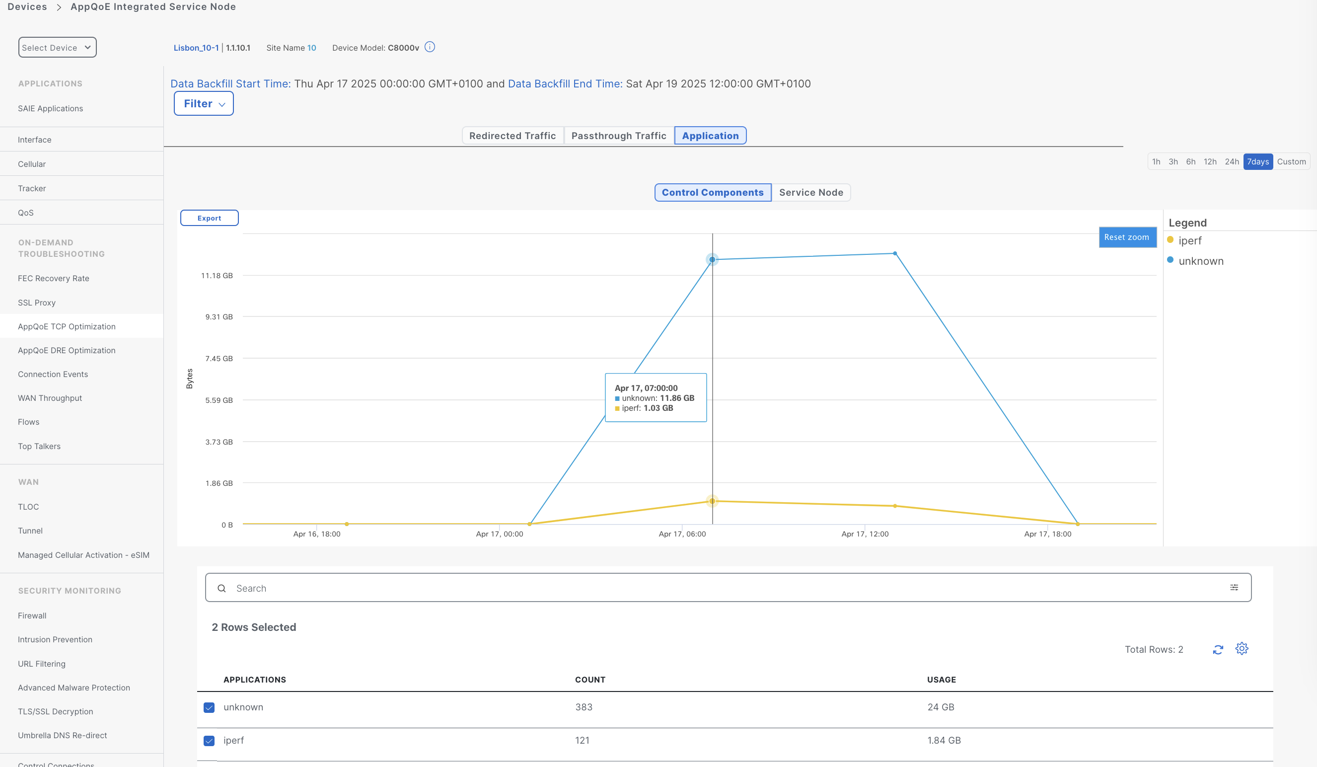
Also, from the real-time information we can see the flow list.
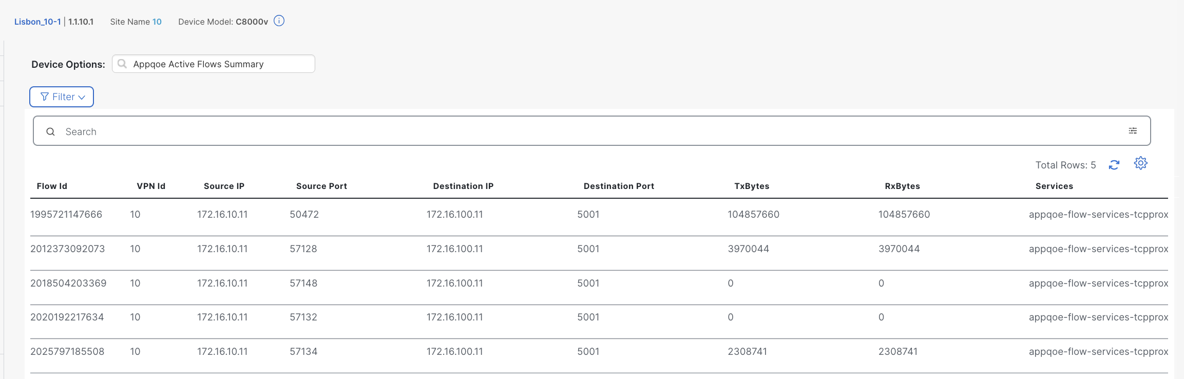
The Services column indicates the TCP Optimization is applied to those flows.
Testing TCP Optimization Performance
To evaluate the impact of TCP Optimization, I ran iperf tests with varying delay parameters to observe where the feature delivers the most benefit. While this isn’t a professional lab setup, it offers valuable information into how the optimization behaves in practice.
Note My iperf traffic is not encrypted. It’s not possible to optimize encrypted traffic without TLS/SSL Decryption
Some testing details:
- Throughput is capped at 250 Mbps on the routers.
- I used 4 parallel streams, each simulating a 100 MB download:
iperf -c 172.16.100.11 -n 100MB -P 4 -i 15 -R
For consistency, I ran each scenario 5 times, discarded the highest and lowest results, and averaged the remaining 3 samples
The following table shows the results:
| Delay | TCP Opt | BW (Mbps) | Time (s) |
|---|---|---|---|
| 0 | Disabled | 248 | ~ 13 |
| 0 | Enabled | 121,6 | ~ 27 |
| 50 | Disabled | 99,7 | ~ 33 |
| 50 | Enabled | 124 | ~ 26 |
| 100 | Disabled | 71 | ~ 46 |
| 100 | Enabled | 131 | ~ 25 |
| 150 | Disabled | 66 | ~ 49 |
| 150 | Enabled | 125 | ~ 26 |
| 200 | Disabled | 59 | ~ 56 |
| 200 | Enabled | 131 | ~ 25 |
| 250 | Disabled | 63 | ~ 52 |
| 250 | Enabled | 126 | ~ 26 |
Here’s a visual representation of the results
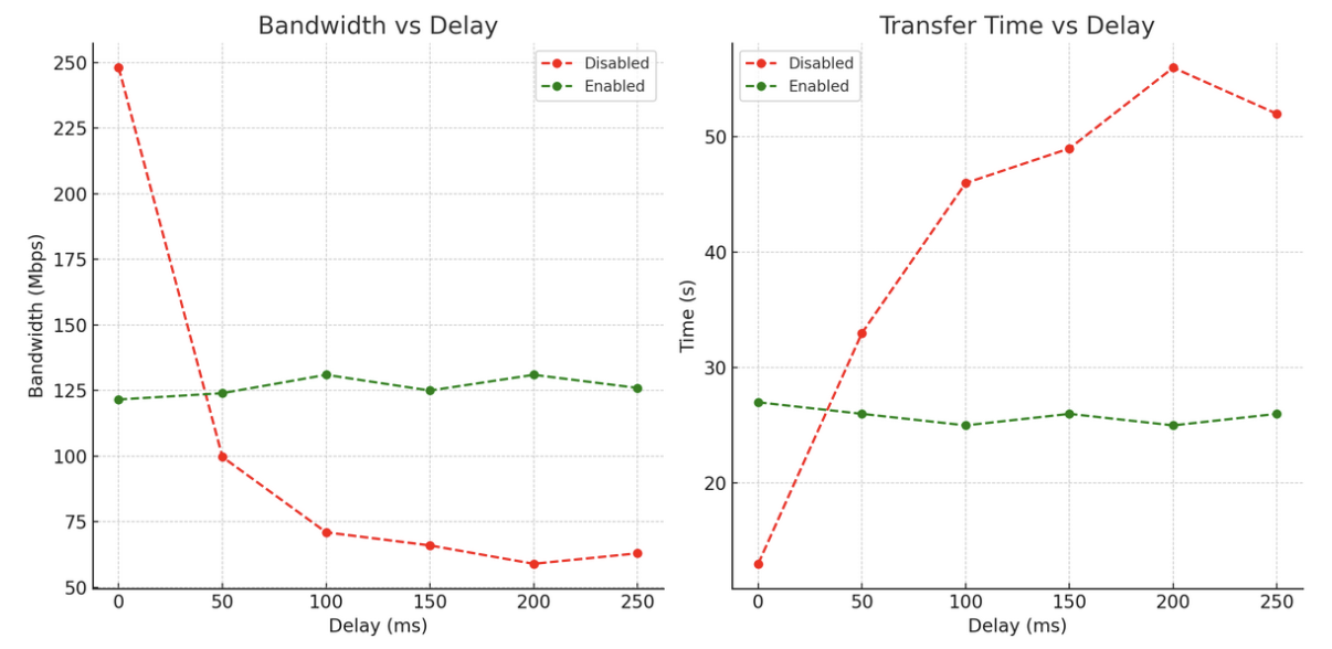
This is what we can conclude from the data:
-
With 0 ms delay, optimization actually reduces performance (121 Mbps vs 248 Mbps), due to overhead introduced by the feature.
-
As delay increases optimization consistently improves throughput and reduces transfer time, this is seen already at 50 ms delay.
-
Performance degrades significantly without TCP optimization. Bandwidth drops from 248 Mbps at 0 ms to ~59–63 Mbps at 200–250 ms. Time also increases proportionally.
-
Performance is stable across different delay values with TCP optimization. Throughput stays around 125–131 Mbps even at high delays. Transfer time is also consistent at around ~26s.
Conclusion
TCP Optimization is highly effective in mitigating the impact of latency on TCP performance. While it introduces some overhead in low-latency conditions, its benefits become more and more evident as delay increases. In scenarios with 100 ms delay or more, optimization can help doubling the throughput and reducing transfer time. If you are thinking about enabling it, take into account that based on the router model, you will get different performance.
Also, this feature shouldn’t be enabled for all traffic, instead enable it for a specific application or set of applications that need acceleration. Finally, this feature brings higher benefits on inter-continental lines, satellite transports or similar high latency links.
Hope this post was useful and see you in the next one!